Table of Contents

Front-end vs Back-End in Semiconductors: 7 Differences

  • The front-end refers to the first stage of the semiconductor fabrication process, when the main structures of the IC such as transistors, resistors or capacitors are fabricated on a silicon wafer using photolithography, etching or deposition processes, among others.
  • The back-end process comes after the front-end, and involves the interconnection, packaging and testing of the manufactured semiconductors.
  • The front-end and back-end are highly interdependent processes. A constant feedback loop between front and back-end engineers is necessary to improve manufacturing yields and make adjustments to semiconductor equipment.

Front-end

Back-end

Creation of the semiconductor structures: transistors, resistors, capacitors etc.

Interconnect the IC to other semiconductor devices to create an IC package. Packaging and testing too.

Wafer cleaning, oxidation, photolithography, etching, deposition, ion implantation and polishing.

Wafer dicing, die attach, interconnection (wire bonding, flip chip, hybrid bonding), encapsulation, testing and packaging.

Very expensive equipment. EUV lithography can cost up to EUR 200 million per machine. Etching and deposition equipment also costly.

Cheaper equipment, in the ballpark of hundreds of thousands USD. Wire bonders, flip-chip bonders, hybrid bonders.

Nanometer (nm) precision required. Important to maximize yield to reduce manufacturing costs and total cost of ownership.

Perfect alignment is required to create reliable IC interconnections, packaging integrity, fast time-to-market and reduce costs.

Very highly skilled engineers and technicians required. Foundries might face shortages of qualified personnel

Less skilled personnel required given it is a less critical process.

Very high upfront investment, around $20 billion for the most modern foundries.

Lower upfront costs, in the single-digit billion dollar range.

Although the front-end and back-end are different parts of the semiconductor manufacturing process, you should think of them as one given there are strong interdependencies among them. Imagine an integrated circuit that is attached to a package using a wire bonding technique, one of the most common back-end assembly methods. During the front-end, the bonding pads are manufactured, which will be further needed during the assembly. If the fron-end process is not precise enough and there is a minor misalignment in the position and layout of the bonding pads, the wire bonding process might also fail, resulting in a defective chip and sunk costs for the semiconductor foundry.

Another example is that front-end engineers must consider the dimensions of the final chip package (back-end). Imagine a SoC that includes several components such as a CPU, memory and I/O ports. Front-end engineers must consider the size and location of each component within the package or the final chip package will be defective, resulting in sunk costs for the foundry due to sloppiness between the front and back-end processes.

Last of all, a successful foundry will have constant feedback loops between front-end and back-end engineers to improve manufacturing processes and yield. Front-end process adjustments are normally made based on results and feedback from back-end testing. With rigorous testing, failures can tracked back to the specific areas of the manufacturing process where they happened, and engineers can make adjustments to front-end processes like refining lithography masks or modifying deposition techniques. Improving semiconductor manufacturing yield is a process that can take months, so a constant feedback between the front and back end is essential.

The Semiconductor Front-End Manufacturing Process

The front-end semiconductor manufacturing process, or front-end-of-line (FEOL), involves many processes, most of them requiring precision in the nanometer range and very expensive equipment like EUV lithography machines, which range from 200 to 400 million euros.

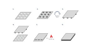
Once the semiconductive silicon wafer is defect-free and ready for IC fabrication, it first goes through the oxidation process. Oxidation is one of the simplest semiconductor manufacturing processes, and it basically consists on applying oxygen to the wafer to create a chemical reaction and deposit a film that will protect the underlying wafer silicon and act as an insulator between transistor gates. The silicon wafer is loaded into a furnace where it is exposed to oxygen gas (and sometimes water steam too, depending if it is dry or wet oxidation) and it is heated at a temperature of 800°C to 1200°C . Once the desired oxide thickness is achieved the furnace is slowly cooled down.

The photolithography and etching processes follow and are normally applied repeatedly after each other, layer by layer. A photoresist (a material that responds to light) is placed on top of the oxidation layer, and the wafer is then exposed to light coming from an extreme ultraviolet (EUV) machine through a reticle or mask, which contains the pattern to be printed. The photolithography process is one of the most critical ones, given it is responsible for printing the nanometer patterns into the wafer that will later act as transistors.

Unnecessary materials and layers are then removed in the etching process, so that only the desired patterns remain in the wafer. This process can be dry etching, which uses reactive gases in plasma form, or wet etching, where a mixture of acids, bases and solvents react with the photoresist material, removing unnecessary parts. For advanced semiconductors (i.e. below the 28nm process node) dry etching is normally the preferred technique given it provides better anisotropy (the material is etched in vertical direction, leaving smooth, vertical sidewalls and a high aspect ratio), and better resolution and critical dimension control.

The deposition process follows the etching, where an insulating layer is applied to the wafer prevent electron leakage. Chemical vapor deposition (CVD) is the most widely used deposition technique, although it is being replaced by atomic layer deposition (ALD) for cutting-edge semiconductors, given the latter allows to create layers one atom thin, allowing for better control and smoother surfaces.

The semiconductor now needs to be charged, given the silicon wafer does not conduct electricity per se, and this is done through ion implantation. This is the process that gives conductivity to the semiconductor by introducing dopant atoms into it.

Once the ion implantation process is finished, a new photoresist is applied to the semiconductor and these processes are repeated once again in a new layer, until all the IC layers have been completed.

Related Posts