Evolution of Metal Pitch in Semiconductor Transistors
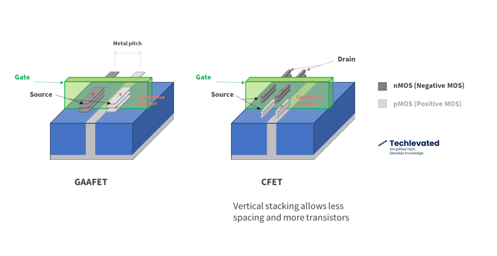
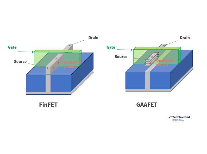
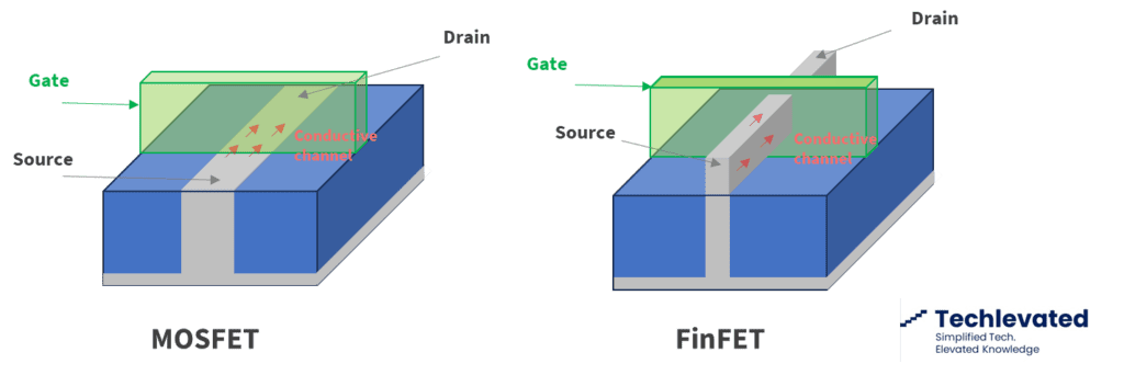
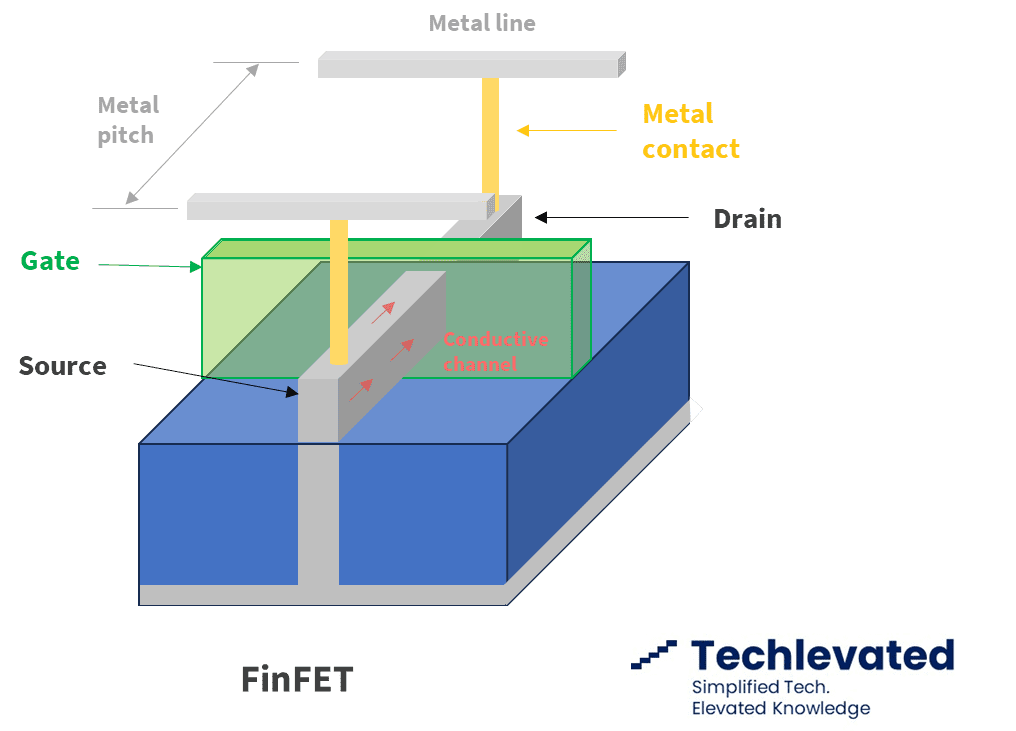
The metal pitch refers to the distance between the centers of two adjacent metal interconnect lines on an integrated circuit (IC). Since transistors evolved into 3D strucrures, this measurement has lost significance.